SystemVerilog Interface
Table of Contents
In Verilog, the communication between blocks is specified using module ports. SystemVerilog adds the interface construct which encapsulates the communication between blocks. An interface is a bundle of signals or nets through which a testbench communicates with a design. A virtual interface is a variable that represents an interface instance. this section describes the interface, interface over traditional method and virtual interface.
Interface Construct
The interface construct is used to connect the design and testbench.
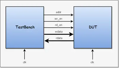
Above diagram shows connecting design and testbench without interface.
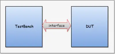
Above diagram shows connecting design and testbench with the interface.
- An interface is a named bundle of wires, the interfaces aim is to encapsulate communication.
- Also specifies the,
- directional information, i.e modports
- timing information, i.e clocking blocks
- An interface can have parameters, constants, variables, functions, and tasks.
modports and clocking blocks are explained in later chapters.
- A simple interface declaration is,
              interface interface_name;
                ...
                interface_items
                ...
              endinterface
- An interface can be instantiated hierarchically like a module, with or without ports.
interface_name inst_name;
- An interface can have parameters, constants, variables, functions, and tasks.
Advantages of the interface over the traditional connection,
- allows the number of signals to be grouped together and represented as a single port, the single port handle is passed instead of multiple signal/ports.
- interface declaration is made once and the handle is passed across the modules/components.
- addition and deletion of signals are easy.
Connecting testbench and design without interface construct,
In the example below,
- Testbench has a design instance and testcase instance, both are connected through wires.
- Inside Testcase, the environment is created and signals are passed to below hierarchy (To drive/sample the stimulus).
- env again passes signals down the hierarchy, and it goes on.
- For any addition or deletion of signal/signals, it is required to add/delete in many places. This problem can be overcome by using an interface construct.
//-------------------------------------------------------------------------
// Verilog Design
//-------------------------------------------------------------------------
module memory ( clk, addr, wr_rd, wdata, rdata);
  input        clk;
  input  [7:0] addr;
  input        wr_rd;
  input  [7:0] wdata;
  output [7:0] rdata;
  ……
endmodule

//-------------------------------------------------------------------------
// TestCase
//-------------------------------------------------------------------------
program testcase ( input bit clk, bit [7:0] addr,bit wr_rd,bit [7:0] wdata,output bit [7:0] rdata);
  environment env; //declaring environment
  initial begin
    env = new(clk, addr, wr_rd, wdata, rdata);
  end
  ……
endprogram

//-------------------------------------------------------------------------
// TestBench Top
//-------------------------------------------------------------------------
module tbench_top;
  //wire declaration
  wire       clk;
  wire [7:0] w_addr;
  wire       w_wr_rd;
  wire [7:0] w_wdata;
  wire [7:0] w_rdata;

  //DUT(Design Under Test) instance
  memory dut(
      .clk(clk),
      .addr(w_addr),
      .wr_rd(w_wr_rd),
      .wdata(w_wdata),
      .rdata(r_data)
      );

  //TestCase Instance
  testcase test(
      .clk(clk),
      .addr(w_addr),
      .wr_rd(w_wr_rd),
      .wdata(w_wdata),
      .rdata(r_data)
  );
 ……
endmodule
Connecting testbench and design with interface construct,
In the below example,
- The interface will group the signals, the handle of an interface is passed across the hierarchy
- Changes made to interface will reflect everywhere
//-------------------------------------------------------------------------
// Verilog Design
//-------------------------------------------------------------------------
module memory ( clk, addr, wr_rd, wdata, rdata);
  input        clk;
  input  [7:0] addr;
  input        wr_rd;
  input  [7:0] wdata;
  output [7:0] rdata;
endmodule

//-------------------------------------------------------------------------
// Interface
//-------------------------------------------------------------------------
interface mem_intf;
  logic      clk;
  logic [7:0] addr;
  logic       wr_rd;
  logic [7:0] wdata;
  logic [7:0] rdata;
endinterface

//-------------------------------------------------------------------------
// TestCase
//-------------------------------------------------------------------------
program testcase (interface  intf);
  environment env;
  initial begin
    env = new(intf);
  end
  ……
endprogram

//-------------------------------------------------------------------------
// TestBench Top
//-------------------------------------------------------------------------
module tbench_top;`
  //Interface instance
  mem_intf intf();

  //DUT(Design Under Test) instance
  memory dut(
    .clk(intf.clk),
    .addr(intf.addr),
    .wr_rd(intf.wr_rd),
    .wdata(intf.wdata),
    .rdata(intf.rdata)
      );

  //TestCase Instance
  testcase test(intf);
  ……
endmodule
Interface example
The below example shows the writing interface, declaration of an interface, connecting the interface with design, and accessing interface signals.
Writing interface
interface intf;

  //declaring the signals
  logic [3:0] a;
  logic [3:0] b;
  logic [6:0] c;

endinterface
Interface declaration
//creatinng instance of interface
intf i_intf();
Connecting interface with design
//DUT instance
adder DUT (
  .a(i_intf.a),
  .b(i_intf.b),
  .c(i_intf.c)
);
Accessing interface signal
i_intf.a = 6;
i_intf.b = 4;

$display("Value of a = %0d, b = %0d",i_intf.a,i_intf.b);
#5;
$display("Sum of a and b, c = %0d",i_intf.c);
Simulator Output
Value of a = 6, b = 4
Sum of a and b, c = 10
Virtual Interface
A virtual interface is a variable that represents an interface instance.
- The virtual interface must be initialized before using it. i.e, Virtual interface must be connected/pointed to the actual interface.
- accessing the uninitialized virtual interface result in a run-time fatal error.
- Virtual interfaces can be declared as class properties, which can be initialized procedural or by an argument to new().
- Virtual interface variables can be passed as arguments to the tasks, functions, or methods.
- All the interface variables/Methods can be accessed via a virtual interface handle. i.e virtual_interface.variable
Syntax
virtual interface_name instance_name;
Virtual interface example
virtual mem_intf intf;